First of all, you need to prepare a structural drawing of your 3D bridge model in 1 : 1 scale, in AutoCad. Then, you may import it into the engineering software and perform the analysis. This method is faster and easy.
a) Prepare 2D AutoCad drawing for analysis:
Convert all the curve lines into straight line as shown in Figure 1 below.
 Figure 1
You have to define clearly (draw) in AutoCad drawing whether you want the crossing members are jointed or not jointed as shown in Figure 2.
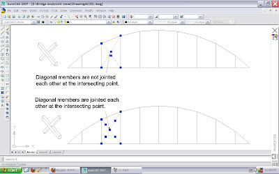 Figure 2
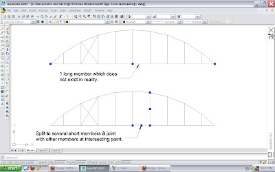 Figure 3
The lines you have to draw must representing the centre line the members, instead of edge line. So, measurement of the whole bridge model must accurate in order to produce accurate analysis.

 Figure 2
As mentioned in the rules, each member should not be greater than 150 mm, therefore you have to break a long member into several shorter members, as shown in Figure 3.
 Figure 3
The lines you have to draw must representing the centre line the members, instead of edge line. So, measurement of the whole bridge model must accurate in order to produce accurate analysis.

Figure 4
Example of finalized 2D drawing with well defined joints.
 Figure 5
b) Convert 2D to 3D:
There are many methods to draw a model into 3D directly. Here is one of the methods:
Switch on the orbit in your toolbox or select View/Orbit/Free Orbit. Rotate to view in 3D. Your bridge is laying on x-y axes.
 Figure 6
Now, we need to duplicate another frame about z axis. Calculate the distance between two centre axes of your frame, let say 95 mm.
 Figure 7
Finish it up with appropriate bracing in 3D. For ease of view, top bracing are in red colour; bottom bracing are in blue colour.
 Figure 8
 Figure 9
Make sure all the lines are joint properly. No overlapping of lines, as it would cause confusion to the analysis software. Then, save your drawing in .dxf format.