ANNOUNCEMENTS

Congratulation! Teams that have confirmed enter to Grand Final are listed as below. The assessments and specification for the bridge model & Poster Presentation are updated at "The Testing" and "Rules & Regulations: Poster Presentation" section. Prizes are revised at "Main Page".

Teams:
  • Babo
  • EnE
  • Fabulous 5
  • PQS Team
  • QS As One
  • The Five
  • Unique

The Grand Final is tentatively planned as below:
Date: 21/1/2011 (Friday)
Time: 2 pm - 5 pm
Venue: B2-L02's Foyer (latest update!)
Attire: Good looking attire
(latest update!)

p/s: if you have classes during that slot, kindly request excuses from your respective lecturers & Head of Programme.

Additional of RM 150 is allocated for each team to prepare their bridge model and poster for the Grand Final. So, total amount for preliminary testing + grand final is RM 350 per team. Please use them wisely!

Table of Content


Welcome to INTI Bridge Model Competition 2010/2011 blog. All information are posted at here. Kindly visit this blog regularly for latest update.


Main Page

In Year 2009, 2007 & 2005, INTI International University has won several prizes in National Bridge Model Competition, which is organised by University Teknologi Malaysia, Johor. It is an intensify and challenging competition. Hence, it provides one of the good opportunities to the students to utilize their knowledge and enhance their soft skills.

INTI Students have won bountiful of prizes in National Bridge Model Competition 2009.

The Faculty of Engineering & Technology is organising an INTI Bridge Model Competition 2010/2011. The aims of this event are:

  1. To encourage students to use knowledge and creativity to solve practical problems.
  2. To discover new and best bridge model design.
  3. To shortlist best candidates to participate next coming National Bridge Model Competition 2011.

The event is tentatively schedule as below:
Deadline of registration : 24/9/2010
Preliminary Testing : 3/11/2010 (3.30 pm - 6.00 pm)
Grand Final : 21/1/2011
(2.00 pm - 5.00 pm) (Updated!)

Attractive Prizes will be awarded to the Top 3 Winners in Grand Final.

First Prize : RM 2000 + Trophy & Medals
Second Prize : RM
1000 + Trophy & Medals
Third Prize : RM 500 + Trophy & Medals
Best Presenter : RM 200 + Trophy (New!)

This competition is open to FOEAT students only. For more information on the competition, kindly read our Rules and FAQ section. The registration form can be achieved at FOEAT office's counter.

Participants are encouraged to access our blog regularly at http://inti-foeat-2010.blogspot.com for further updates and announcements on the competition.

FAQ 2

Q1) Other than the information listed in "Rules & Regulations: Poster Presentation" section, what additional information should I put in?
Any information, data, special ideas or concepts, figures, illustration pictures that can make your team special and win.


Q2) How to make my poster looks attractive and scores more marks?
Design your poster layout using appropriate colours. Pictures must be clear and font size must be readable when it is posted on board. No over cluster of words and data. Arrange your information properly/in order.

Q3)
Can all my members take turn to present?
Yes, you can. But, better make sure all your team members are very good presenters.

Q4) Can I find my friends that not registered in the group to do the presentation?
No. Only registered team members are allowed to present for your team.

Q5) Can I make PowerPoint or Multimedia as part of my presentation?
It is only can use for attracting and presenting to the audience, but not to the judges. Besides, judges will not giving extra time & marks for your PowerPoint or Multimedia presentation. But, you still can show your best effort so that we can tape your talent.

Q6) I really want to make PowerPoint or Multimedia to attract the audience. How long shall it be?
It depends on you.

Q7) Can I use hand drawing to draw my illustration, and then paste it on my poster?
Yes, you can. However, it is recommended to use graphical software to draw it if you are not a good artist. You also can find some of the illustration pictures regarding to future development project from Internet.

Q8) How the organiser determine the Best Presenter(s)?
Those who scores highest marks in Poster Presentation section will be awarded Best Presenter(s).

Q9) What elements are going to be assessed in Poster Presentation section?
INTI International University always emphasizing the important of soft skills, rather than just academic. Therefore, we are going to assess your poster design, contents and grammar, presentation contents and skills, technical knowledge, fluency of English language, and ability to answer the questions logically and confidently. Detail break down of marks will be uploaded later.


TUTORIAL 2:

a) Import .dxf into StaadPro:

Whenever the StaadPro is launched, a small "New" window panel will automatically open. Cancel it and we want to import .dxf drawing. Select File/Import. Then, select "Import 3D DXF" from your directory.

Figure 1

Remain "No Change" in the "Structure Convention", as shown in Figure 2. Preferably, set units to be used are mm & kN or N.

Figure 2

Hurray! You have done it. And, it should looks like this. The red line shows a diagonal member. While, each member can be selected at here. Explore all the functions by yourself and this is so call "self-learning".

Figure 3

Select "Geometry" & "Beam" functions. You will see the model with a lot of dots, as shown in Figure 4. There are called as nodes, which mean the end point/connecting point of the member with other members.

Figure 4

b) Define the bridge model:

Select "General" function. In this interface, we need to define the property, support, load & material used in this model.

i) Click "Material" and you can notice Balsa wood is not available in the material list, as shown in Figure 5. Therefore, we need to create a new material with relevant properties. Key in all the data, as shown in Figure 5. Based on our research (trial & error + on site verification), those value able to generate accurate result.

Figure 5

Then, select "Balsa" and "Assign To View", subsequently click "Assign", as shown in Figure Q6.

Figure 6

ii) Click "Property" and define the dimension & properties for the relevant members. If your arch is in 5 mm x 15 mm and others member are in 5 mm x 5 mm, then you should add another 5 mm x 5 mm property later on. Close the window box after you have finished the definition.

Figure 7

Assign the arch, internal members and bracing with relevant sizes as you want.

Figure 8

Remember to save your project!!

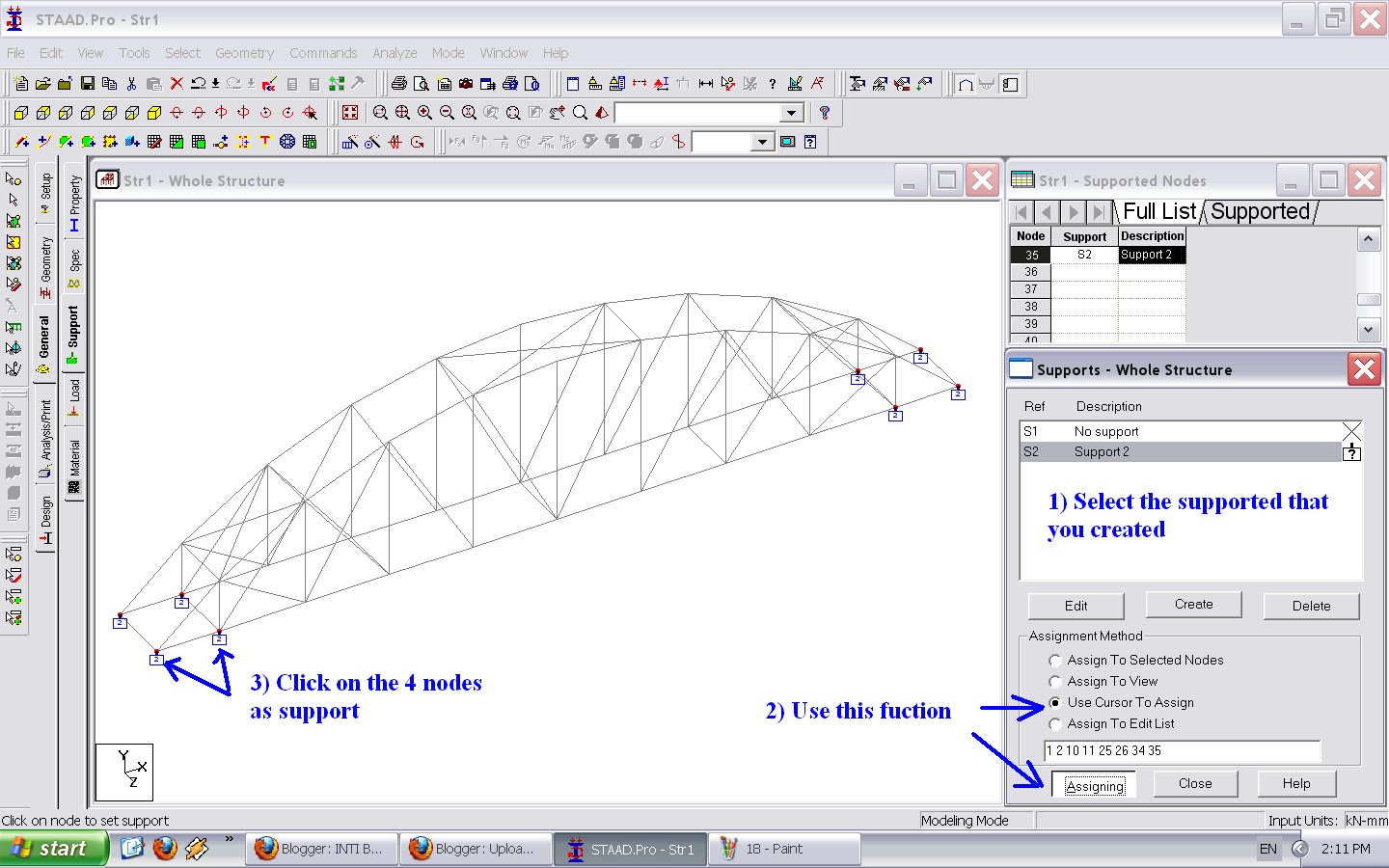
ii) Click "Support" and create the support you want. An example is shown in Figure 9. You may change it according to your bridge design, but most of the bridge model should be supported as in this example.

Figure 9

Assign supports into your model.

Figure 10

c) Assign the loads:

Let say a member is drawn from left to right in AutoCad, such as from node 1 to node 2. And, a Point load has to be acted 25 mm apart from left on the member. Then, inserting a point load with a distance of 25 mm (inside the StaadPro) will make the point load acts 25 mm apart from the starting point of the beam. Refer Figure 11.
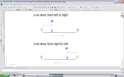
Figure 11

i) Select "Load" interface and type in the title of the load.

Figure 12

ii) Select "Member" and choose "Concentrated Force" tab. Set the information, where negative value means the load is pointing downward. The point load should be acting 150 mm from the centre, as per the testing rules. Since d1 distance depends on how you draw the line in AutoCad, so you may need trial & error method to get the outcome you want.

*[(5kg / 4) x 9.81] /1000 = 0.013 kN (round up)

Figure 13

I created two similar loads as shown in "Load Specification" box (Figure 14), since d1 distance is difference.

Figure 14

d) Run Analysis:
Yeah! The modeling is almost complete. Couldn't wait longer to see your result? Hold on, you have to add a command so that the programme can execute it, as shown in Figure 15.
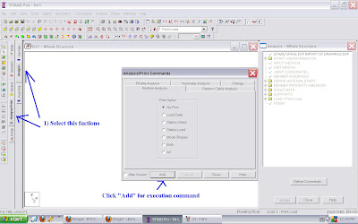
Figure 15

After that, select Analyze/Run Analysis... to perform the structure analysis.
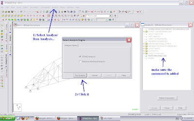
Figure 16

If you got some error at this stage, you have to figure out what and where is the problem. Worst come to worst, you have to redo the model or redraw the drawing (may cause by the lines are not jointed properly in AutoCad. Use ONSNAP setting properly).
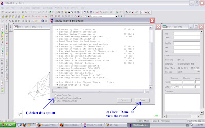
Figure 17

e) The Analysis Results:

The results can be showed in:

i) The displacement of nodes.
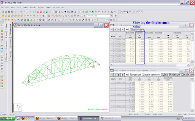
Figure 18

Use cursor to click the point you wish to know its deflection value.
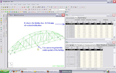
Figure 19

ii) Forces in beams.
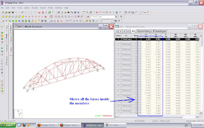
Figure 20

iii) Animation.

Figure 21

If you do not satisfy with your design, you have to change the design in AutoCad. Then, import it into StaadPro and perform the modeling again.

Good Luck!

TUTORIAL 1:

These tutorials are prepared for those who wish to use engineering software (StaadPro) to analyze your bridge structure.

First of all, you need to prepare a structural drawing of your 3D bridge model in 1 : 1 scale, in AutoCad. Then, you may import it into the engineering software and perform the analysis. This method is faster and easy.

a) Prepare 2D AutoCad drawing for analysis:

Convert all the curve lines into straight line as shown in Figure 1 below.

Figure 1

You have to define clearly (draw) in AutoCad drawing whether you want the crossing members are jointed or not jointed as shown in Figure 2.

Figure 2

As mentioned in the rules, each member should not be greater than 150 mm, therefore you have to break a long member into several shorter members, as shown in Figure 3.

Figure 3

The lines you have to draw must representing the centre line the members, instead of edge line. So, measurement of the whole bridge model must accurate in order to produce accurate analysis.

Figure 4

Example of finalized 2D drawing with well defined joints.

Figure 5


b) Convert 2D to 3D:

There are many methods to draw a model into 3D directly. Here is one of the methods:

Switch on the orbit in your toolbox or select View/Orbit/Free Orbit. Rotate to view in 3D. Your bridge is laying on x-y axes.

Figure 6

Now, we need to duplicate another frame about z axis. Calculate the distance between two centre axes of your frame, let say 95 mm.

Figure 7

Finish it up with appropriate bracing in 3D. For ease of view, top bracing are in red colour; bottom bracing are in blue colour.

Figure 8

Figure 9

Make sure all the lines are joint properly. No overlapping of lines, as it would cause confusion to the analysis software. Then, save your drawing in .dxf format.

Kindly read Tutorial 2 for structure analysis.

Photos

Some photos have been taken from previous Bridge Model Competitions. You may get some idea at here or improve the design, but do not copy 100%.