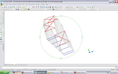
Whenever the StaadPro is launched, a small "New" window panel will automatically open. Cancel it and we want to import .dxf drawing. Select File/Import. Then, select "Import 3D DXF" from your directory.
Remain "No Change" in the "Structure Convention", as shown in Figure 2. Preferably, set units to be used are mm & kN or N.
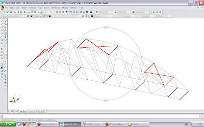
Hurray! You have done it. And, it should looks like this. The red line shows a diagonal member. While, each member can be selected at here. Explore all the functions by yourself and this is so call "self-learning".
Select "Geometry" & "Beam" functions. You will see the model with a lot of dots, as shown in Figure 4. There are called as nodes, which mean the end point/connecting point of the member with other members.
b) Define the bridge model:
Select "General" function. In this interface, we need to define the property, support, load & material used in this model.
i) Click "Material" and you can notice Balsa wood is not available in the material list, as shown in Figure 5. Therefore, we need to create a new material with relevant properties. Key in all the data, as shown in Figure 5. Based on our research (trial & error + on site verification), those value able to generate accurate result.
Then, select "Balsa" and "Assign To View", subsequently click "Assign", as shown in Figure Q6.
ii) Click "Property" and define the dimension & properties for the relevant members. If your arch is in 5 mm x 15 mm and others member are in 5 mm x 5 mm, then you should add another 5 mm x 5 mm property later on. Close the window box after you have finished the definition.
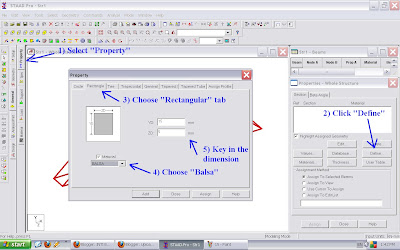 Figure 7
Remember to save your project!!
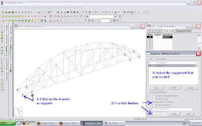
ii) Click "Support" and create the support you want. An example is shown in Figure 9. You may change it according to your bridge design, but most of the bridge model should be supported as in this example.
Figure 9
Figure 10
c) Assign the loads:
Let say a member is drawn from left to right in AutoCad, such as from node 1 to node 2. And, a Point load has to be acted 25 mm apart from left on the member. Then, inserting a point load with a distance of 25 mm (inside the StaadPro) will make the point load acts 25 mm apart from the starting point of the beam. Refer Figure 11.
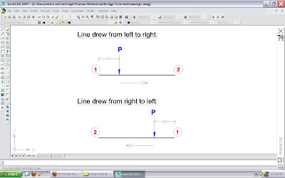 Figure 11
ii) Select "Member" and choose "Concentrated Force" tab. Set the information, where negative value means the load is pointing downward. The point load should be acting 150 mm from the centre, as per the testing rules. Since d1 distance depends on how you draw the line in AutoCad, so you may need trial & error method to get the outcome you want.
*[(5kg / 4) x 9.81] /1000 = 0.013 kN (round up)
I created two similar loads as shown in "Load Specification" box (Figure 14), since d1 distance is difference.
d) Run Analysis:
Yeah! The modeling is almost complete. Couldn't wait longer to see your result? Hold on, you have to add a command so that the programme can execute it, as shown in Figure 15.
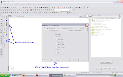 Figure 15
After that, select Analyze/Run Analysis... to perform the structure analysis.
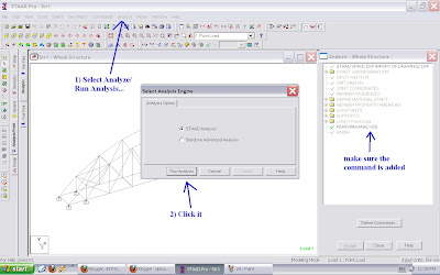 Figure 16
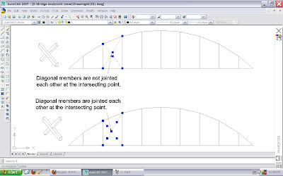
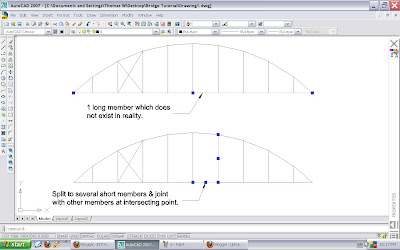
If you got some error at this stage, you have to figure out what and where is the problem. Worst come to worst, you have to redo the model or redraw the drawing (may cause by the lines are not jointed properly in AutoCad. Use ONSNAP setting properly).
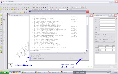 Figure 17
e) The Analysis Results:
The results can be showed in:
i) The displacement of nodes.
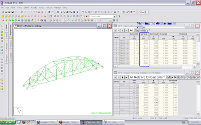 Figure 18
Use cursor to click the point you wish to know its deflection value.
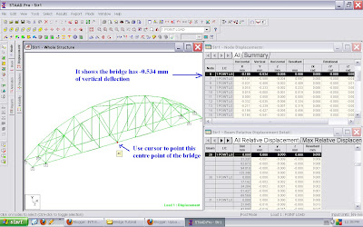 Figure 19
ii) Forces in beams.
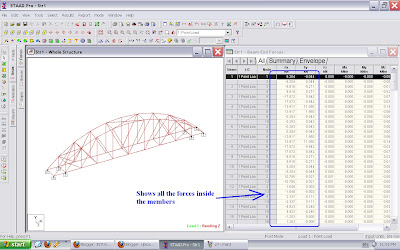 Figure 20


